Compound Parabolic Concentrator Cross-Sections and 3D-Printed Designs for Solar Thermophotovoltaic Systems
Background
The Shockley–Queisser limit predicts the theoretical maximum efficiency of single-junction solar cells to be approximately 31%, due to the mismatch between the Sun’s broadband spectrum and the silicon bandgap. Solar thermophotovoltaic systems present an advantage over photovoltaic systems here: they use an intermediate absorber and emitter that allow the emission spectrum to be tuned, so more of what reaches the cell arrives at a wavelength it can use. That raises the theoretical ceiling to roughly 85% under ideal conditions — at which an area the size of New Jersey could meet the electrical power demands of Earth’s entire population and industries.
Laboratory STPV systems have achieved efficiencies as high as 42% using III–V photovoltaic cells and selective emitters, but these systems can be impractical and expensive due to the low availability of materials.
This study investigates the role of the compound parabolic concentrator (CPC) and the absorber/emitter material in the STPV system, and their impact on system performance under practical operating conditions.
Understanding the system
A solar thermophotovoltaic (STPV) system converts sunlight into heat and re-emits it as infrared radiation matched to the PV cell bandgap.
The STPV system includes a concentrator, an absorber, an emitter, and a PV cell. Concentrated sunlight is absorbed as heat, then emitted toward the PV cell. To prevent thermal damage to the PV cell, a heat sink is attached to the back, allowing it to cool through convection.

Concentrator. Focuses sunlight on to the absorber.
Absorber. Converts concentrated sunlight into heat.
Emitter. Radiates thermal energy towards PV cell at wavelengths close to bandgap.
PV Cell. Semiconductors that absorb photons above their bandgap to convert to energy into electricity.
Heat Sink. Dissipates heat from PV cell to maintain efficiency.
Methods
Traditionally, concentrators are primarily Fresnel lenses, parabolic dishes, or CPCs, commercially available but often prohibitively expensive. We chose to work with the CPC as it offered more design flexibility than other concentrators, and fabricated custom CPCs through 3D printing.
We conducted a parameter sweep over the shape of the concentrator cross-section — circle, ellipse, rectangle — along with acceptance angle and the relevant dimensions: radius of the circle, major and minor diameter for the ellipse, length and width for the rectangle. Notably, we introduced the parameter split, which allowed larger concentrators to be fabricated as an attachment of two separately printed components (in regard to CAD, not the print bed).
Split. For both circular and elliptical CPCs, a 2-piece split print was predicted to increase system efficiency by 69%.

Acceptance Angle. A large acceptance angle increases ability to use the design throughout the day, making it more practical for usage, but it also reduces efficiency. Elliptical designs, able to maintain a wide East-West angle alongside a narrow North-South angle, showed more resistance to this change.

Two concentrators were fabricated for testing: a circular CPC with radius 74.265 mm and an acceptance angle of 20°, and an elliptical CPC (split) with major and minor radii of 100.64 mm and 98.14 mm, and acceptance angles of 15° and 10° along the major and minor axes respectively.
Assembly Rig: CAD with Autodesk Fusion. Variable heights: 1 mm, 2 mm, 4 mm, 8 mm, 16 mm.

Concentrators. Designed in CAD with the Cadquery library for Python. Two were fabricated for testing: a circular CPC as the control, and an elliptical CPC printed in two interlocking parts so that a longer concentrator would fit the print bed.

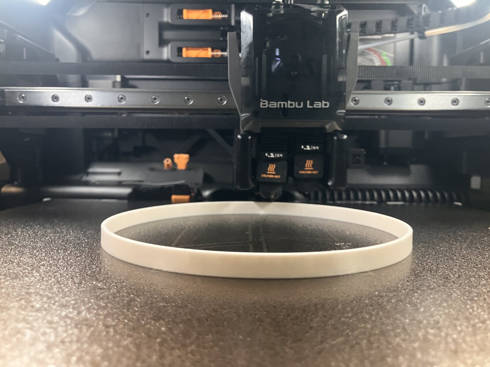
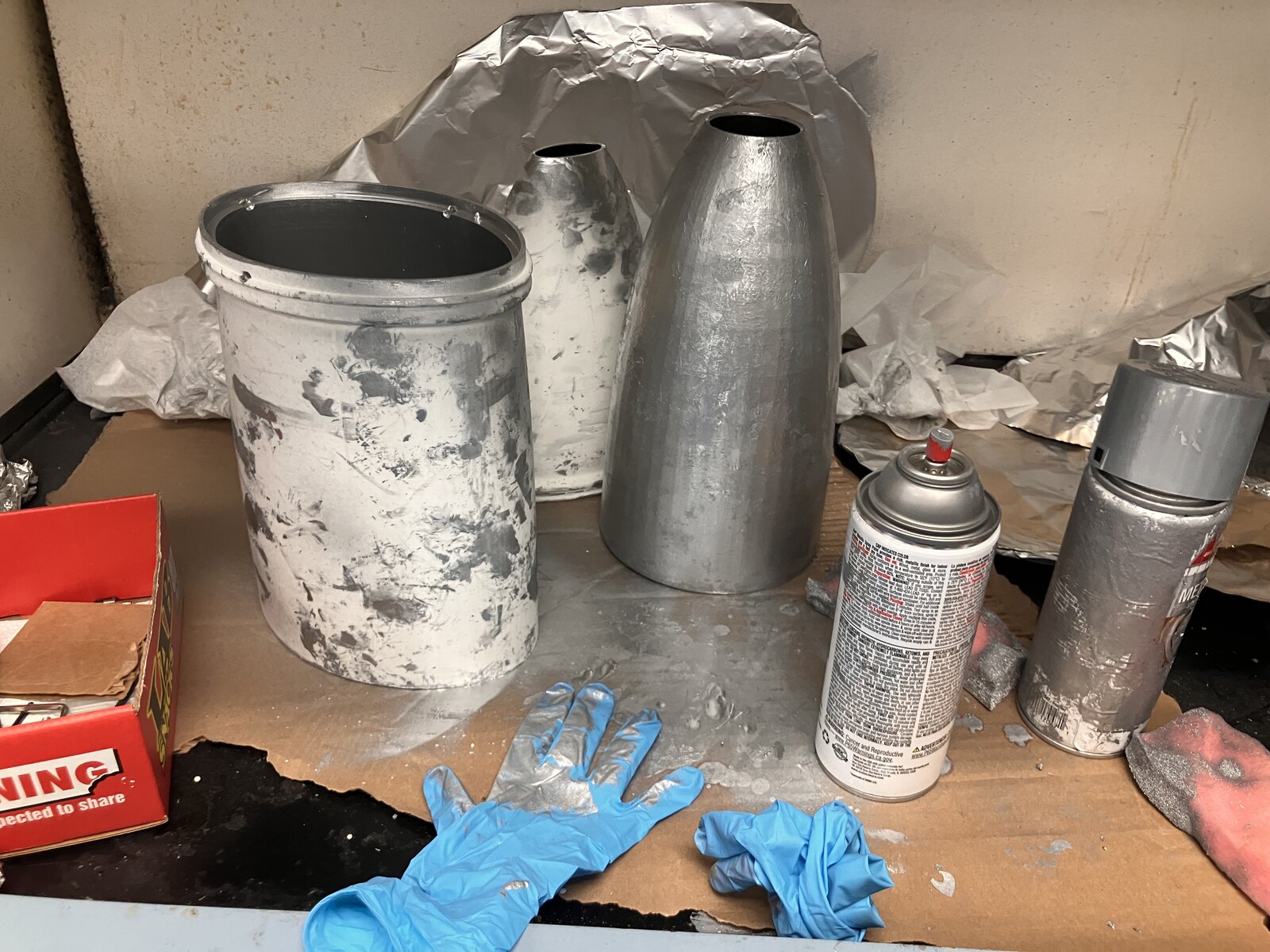
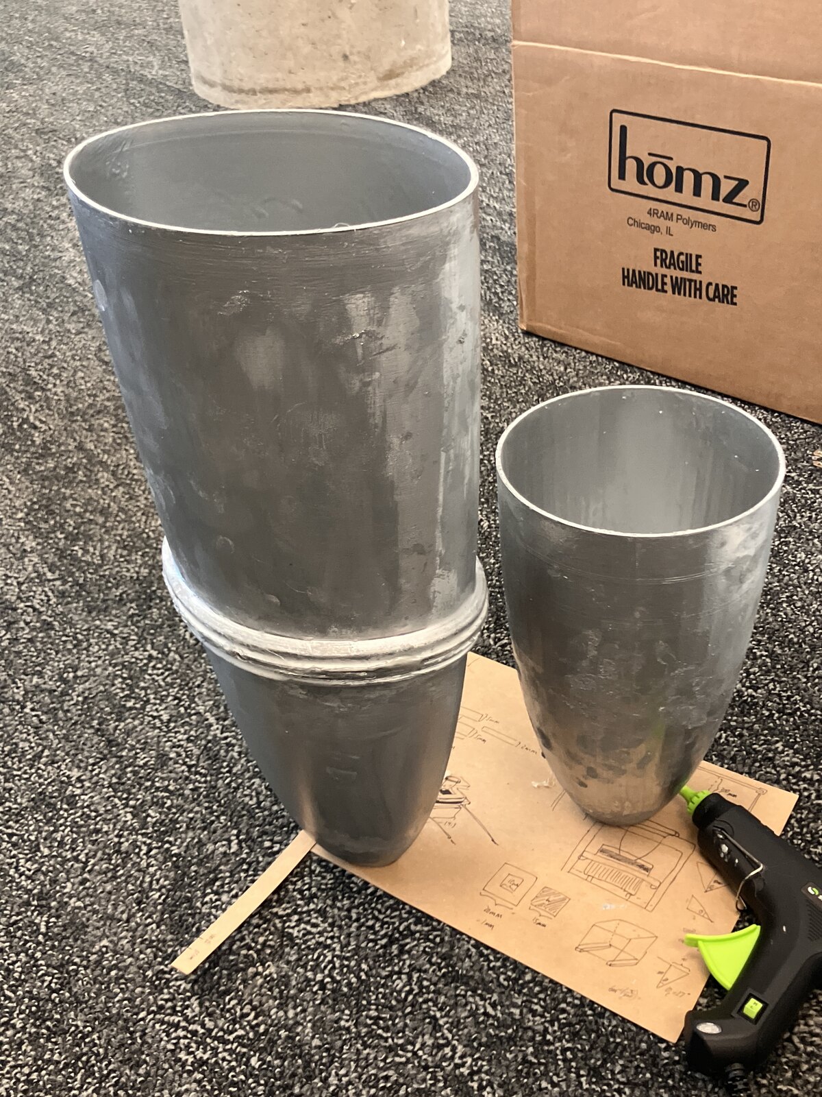
Figure 7. Printing, chrome spray coating, and the finished pair.

Testing
These concentrators were tested outdoors on a 1 cm x 1 cm one-sided anodized (blackened) aluminum sheet against each other.
Indoors, we evaluated the use of different absorber/emitter materials: a 3 in x 3 in silicon carbide (SiC) sheet, a 3 in x 3 in SiC sheet painted black on the absorber side, a 1 cm x 1 cm SiC sheet, a 1 cm x 1 cm SiC sheet painted black, and a 1 cm x 1 cm one-sided anodized aluminum sheet.
For each of these scenarios, system efficiency is calculated as the ratio of power output to power input. We connected the PV cell to a circuit that measures the current and voltage through a range of load resistance and determined the system’s maximum power. Because the weather was partly cloudy on the day of outside measurement, the solar irradiance was estimated from the measurements obtained with the PV cell and manufacturer specifications regarding efficiency.
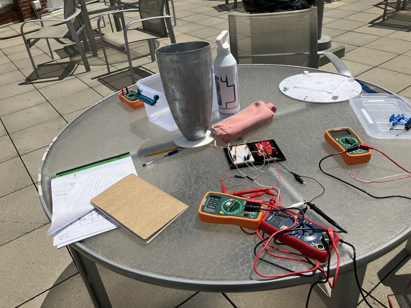
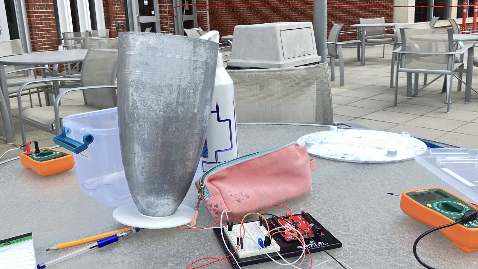
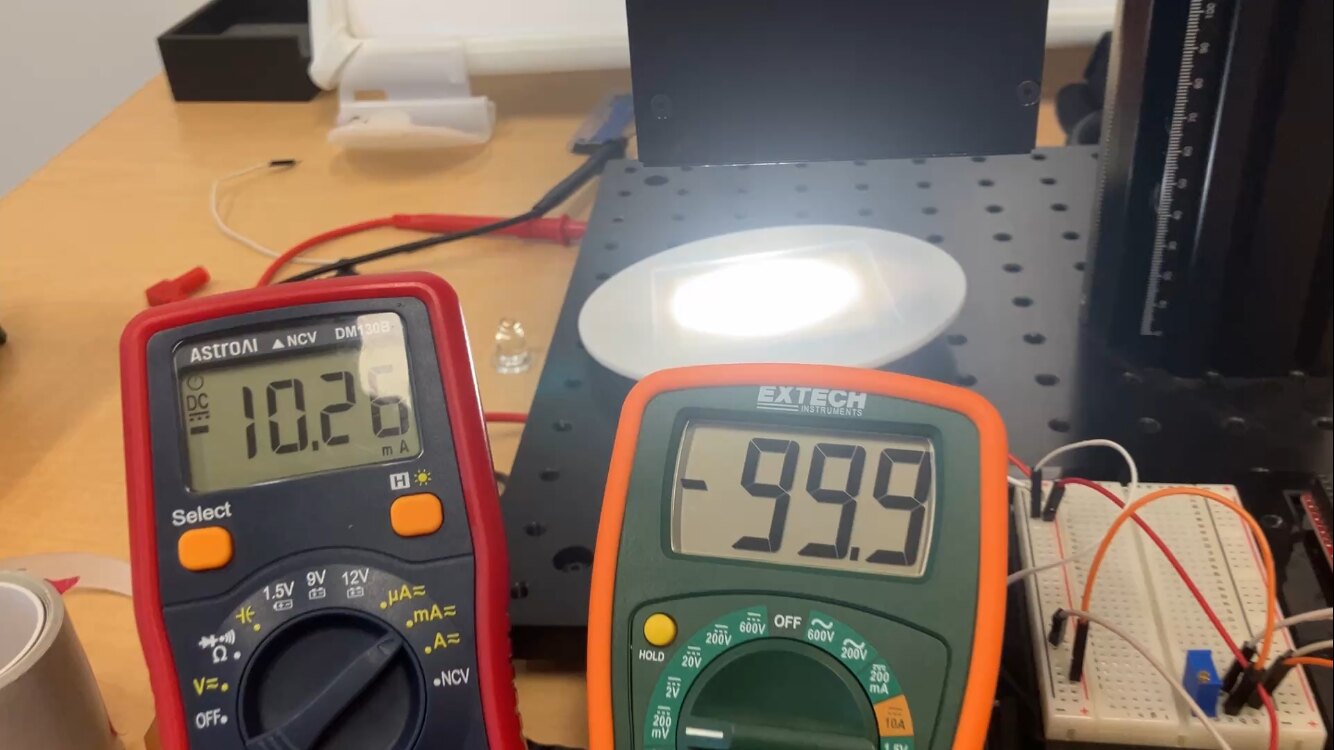
Figure 9. (a, b) Outdoor testing setup. (c) Indoor testing setup.
Results
Indoors
The 3 in × 3 in SiC absorbers produced no measurable electrical output. Among the 1 cm × 1 cm samples, the painted SiC achieved the highest efficiency (4.06%) and maximum power (4.48 mW), followed by the unpainted SiC (3.85%, 4.25 mW) and anodized aluminum (3.68%, 4.06 mW).

Outdoors
Using the PV cell directly with the sunlight, and accounting for its efficiency information from the manufacturer, I calculated the solar irradiance to be 502.5 W/m². With the anodized aluminum and the 2 mm cavity distance, the circular CPC had an efficiency of 0.35% and a maximum observed power output of 30.1 mW; with optimized load resistance the system could theoretically produce 31.63 mW. The elliptical CPC performed slightly better, with an efficiency of 0.496% and an observed power output of 14.4 mW. It had greater potential for improvement, however, with a theoretical efficiency of 2.1% and a maximum power output of 43.25 mW, assuming optimized load resistance under the measured irradiance conditions.
Under optimized resistance the elliptical CPC could achieve an efficiency as high as 2.1% compared to 0.36% for the circular CPC, and a maximum power output of 43.25 mW compared to 31.1 mW.

Discussion
Novelty. Previous 3D-printed CPCs were limited to circular cross-sections. The usage of a male-female interlocking geometry enables printing a longer elliptical CPC shown to achieve a theoretical efficiency of 2.1% under optimized resistance for a silicon PV cell-anodized aluminum absorber/emitter system.
Limitations. The system used a silicon PV cell instead of the higher-efficiency InGa cells typically used in STPV systems due to cost constraint. In addition, the emitter–PV cell spacing was not optimized, reducing radiative coupling efficiency. Finally, the chrome spray coating (~50% reflectivity) lowered concentrator optical efficiency.
Conclusions. This work demonstrates a practical split-and-join fabrication approach for 3D-printed CPCs. Comparing two designs, a split-elliptical CPC and a circular CPC, we find the elliptical design to show more potential for growth in terms of power output and efficiency. Future research could investigate split-and-join, specifically elliptical designs, for cheap and quick fabrication in STPVs.