Smartphone Cardboard Robot
| Engineer | School | Area of Interest | Grade |
|---|---|---|---|
| Mihika K | Los Altos High School | -check before publishing- NOT SURE | Incoming Junior |
![]()
Final Milestone
Second Milestone
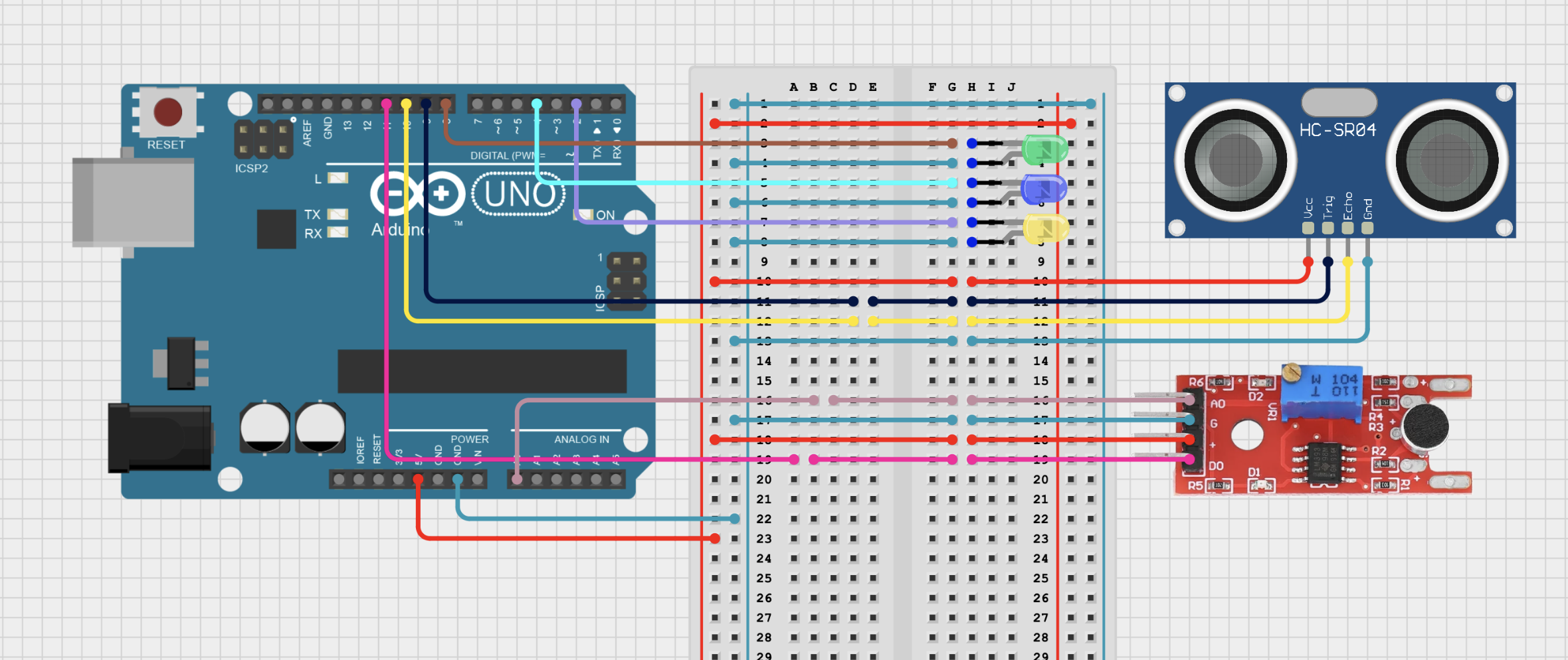
Description: For this milestone, I have implemented the sensors that will be part of the final Cardboard Robot. Originally, I had intended to make the robot walk, but due to the weight and problems with the robot’s balance, I pivoted to adding sensors so the robot can respond to outside inputs. The circuit in the video demonstrates the usage of the Ultrasound Sensor, and the Microphone. The Ultrasound Sensor works by emitting a frequency of 40 kHz, and measuring the time it takes for the sound to be echoed back. Using the speed of sound, it estimates the distance it is from an object. Note that the speed of sound is about 343 m/s, meaning that this measurement is quite accurate for most moving objects (only planes and rockets can break Mach 1, and they’re irrelevant for this project). The Microphone works with two outputs, digital and analog, allowing the analysis of the exact volume, as well as whether there is a significant sound or not.
Status: In this particular circuit, the lightbulbs turn on in response to the sensors (red turns on when the Ultrasound Sensor detects an object between 10 and 30 centimeters from it, blue turns on if it detects an object within 10 centimeters, and green turns on in response to a lound sound). Although these lightbulbs won’t be in the final robot, the robot will have its own reactions to external stimuli.
Challenges: This milestone required me to consider the specifications of the Ultrasound Sensor, and the Microphone, which I had never used before. The microphone particularly didn’t have a lot of documentation online, so I brainstormed how I could analyze the Analog output to differentiate sounds of different levels. By adjusting its sensitivity, I set the microphone so that it could hear detect a person talking.
Plan: I plan on integrating these sensors with the larger robot, so that he can respond to inputs from these sensors. In addition I plan on completing and soldering the circuits.
Code for Sensor Testing
const int TRIG = 9;
const int ECHO = 6;
const int REDPIN = 13;
const int GREENPIN = 8;
const int BLUEPIN = 12;
int micAnalog = A0;
int micDig = 2;

float analogVoltage;
int digValue;
float duration, distance;

unsigned long prevMillisLow = 0;
unsigned long prevMillisHigh = 0;

void setup() {
  pinMode(micAnalog, INPUT);
  pinMode(micDig, INPUT);
  pinMode(TRIG, OUTPUT);
  pinMode(ECHO, INPUT);
  Serial.begin(9600);
  digitalWrite(REDPIN, LOW);
  digitalWrite(BLUEPIN, LOW);
  digitalWrite(GREENPIN, LOW);
}

void loop() {
  unsigned long currentMillis = millis();
  digitalWrite(TRIG, LOW);
  //replacement for delay-- (2 milliseconds)
  if (currentMillis - prevMillisLow >= 2) {
    prevMillisLow = currentMillis;
    digitalWrite(TRIG, HIGH);
  }
  //replacement for delay-- (10 milliseconds)
  if (currentMillis - prevMillisHigh >= 10) {
    prevMillisHigh = currentMillis;
    digitalWrite(TRIG, LOW);
    duration = pulseIn(ECHO, HIGH);
    distance = (duration*.0343)/2;
    Serial.print("Distance: ");
	  Serial.println(distance);

    if (distance < 10){
      digitalWrite(BLUEPIN, HIGH);
      digitalWrite(REDPIN, LOW);
    } else if (distance < 30){
      digitalWrite(REDPIN, HIGH);
      digitalWrite(BLUEPIN, LOW);
    } else {
      digitalWrite(REDPIN, LOW);
      digitalWrite(BLUEPIN, LOW);
    }
  }

  analogVoltage = analogRead(micAnalog) * (5.0/1023.0);
  digValue = digitalRead(micDig);
  Serial.print("Analog Voltage Value: ");
  Serial.println(analogVoltage);
  if (analogVoltage > 0.20){
    digitalWrite(GREENPIN, HIGH);
  } else {
    digitalWrite(GREENPIN, LOW);
  }
}
First Milestone
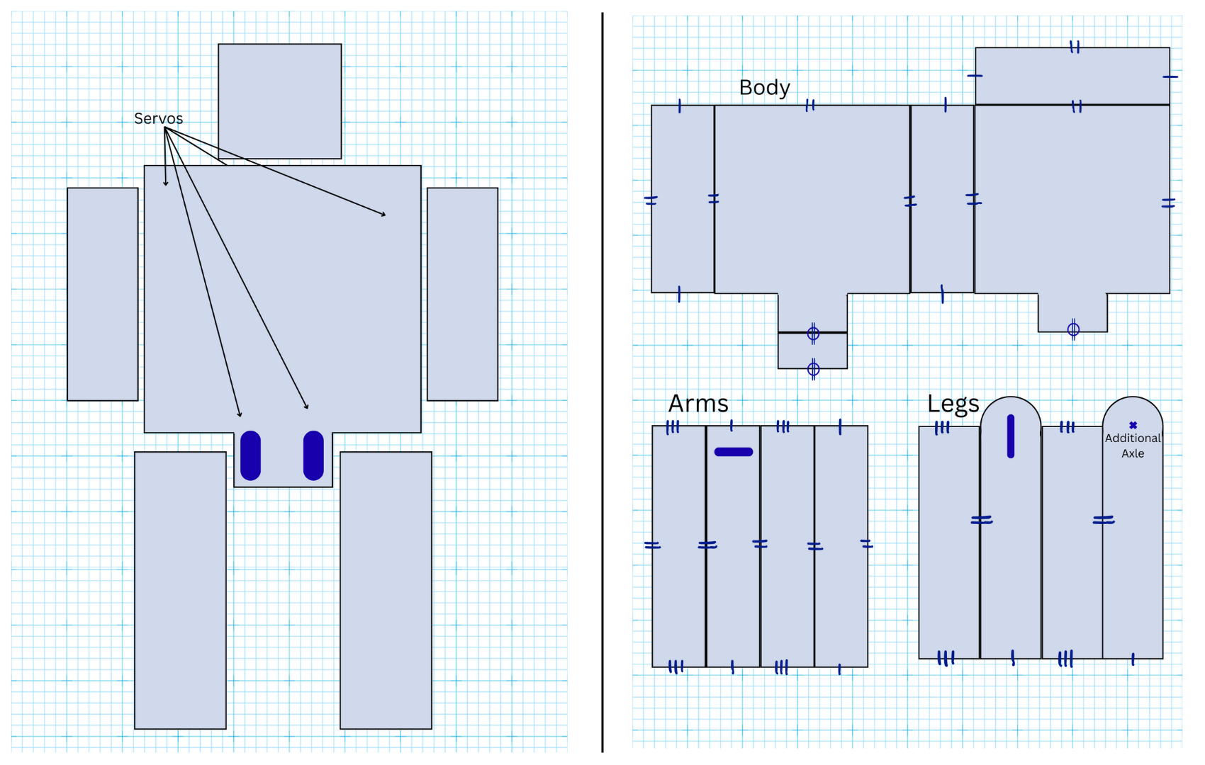
Description: The Smartphone Cardboard Robot is built with servos, LEDs, an electrical circuit, and encased with cardboard blocks. Each of the servos allow the movement of the head, the arms, and legs. LEDs in the head simulate eyes, and will blink in different patterns to indicate different modes. The nets and movement models explain the structure of each cardboard limb as well as the body of the robot. As part of this milestone, I tested the servos and their ability to move the cardboard limbs (see schematics and diagrams below).
Status: As of the first milestone, I have completely built the robot’s cardboard body, as well as positioned and attached all the servos. This includes considering movement of the robot’s limbs and modifying parts of the body to allow for that. For example, the are actually attached to the body with a semicircle shape at the top allowing it to rotate easily.
Challenges: One challenge I’m facing is the robot’s stability. While modifying the legs allowed the robot to actually move its legs, it dramatically reduced the robot’s stability due to there only being one point of contact between the legs and the body. Another challenge is considering the placement of the electrical circuit so the robot does not topple.
Plan: Later on, I plan to complete the circuit of the robot with the LEDs, and code the app on the smartphone to control the robot. In addition, I plan on adding a motion sensor and sound sensor so that the robot moves towards motion, and stops at sounds above a certain decibel value.
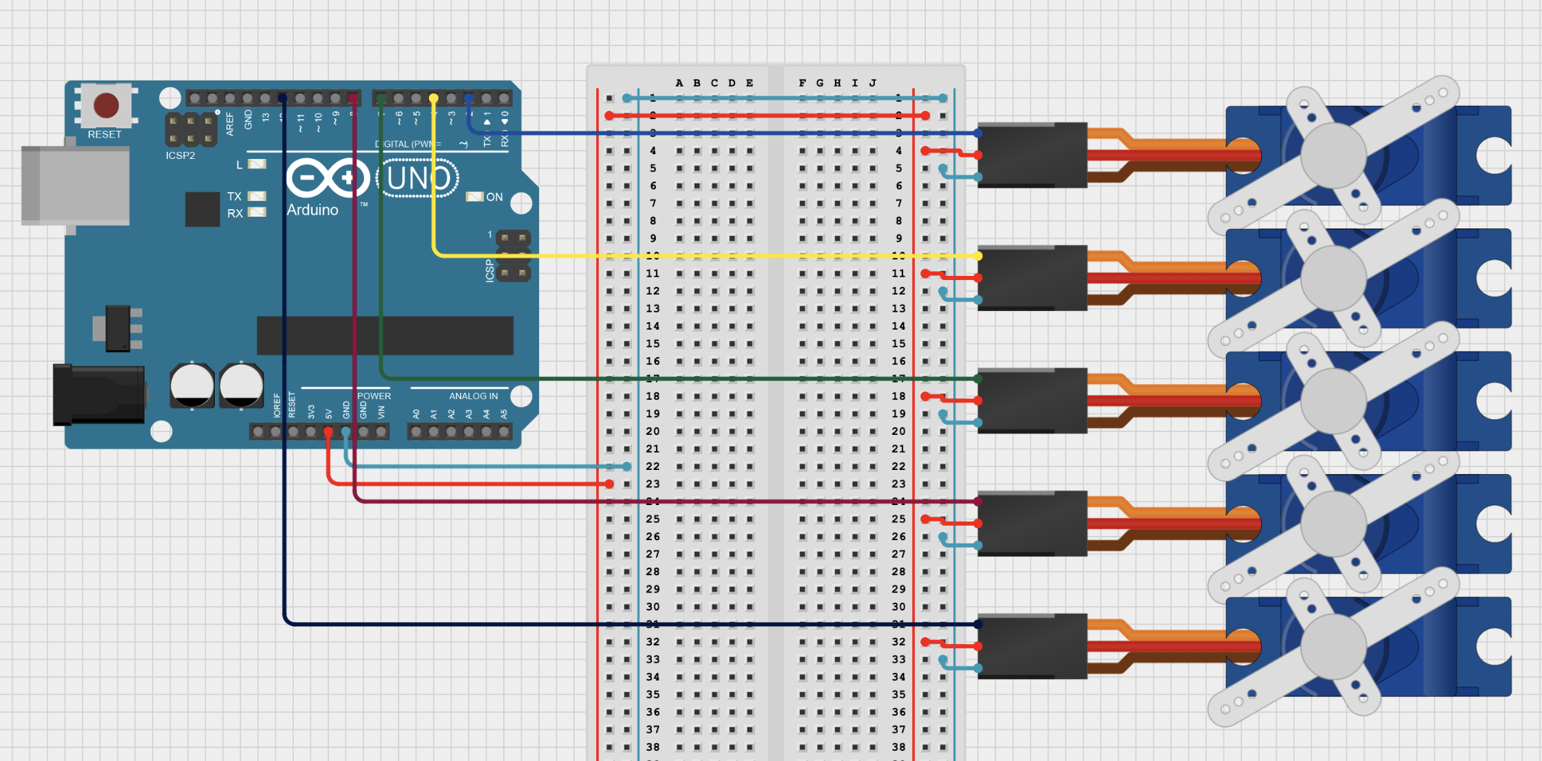
Code for Servo Testing
#include <Servo.h>

const int LL_PIN = 2;
const int LA_PIN = 4;
const int RL_PIN = 7;
const int RA_PIN = 8;
const int HEAD_PIN = 12;
Servo leftLeg, leftArm, rightArm, rightLeg, head;

void setup() {
  leftLeg.attach(LL_PIN);
  leftArm.attach(LA_PIN);
  rightLeg.attach(RL_PIN);
  rightArm.attach(RA_PIN);
  head.attach(HEAD_PIN);
  reset();
  }

void loop() {
  leftLeg.write(180);
  delay(1000);
  rightLeg.write(0);
  delay(1000);
  leftArm.write(90);
  delay(1000);
  rightArm.write(90);
  head.write(180);
  delay(1000);
  reset();
}

void reset(){
  leftLeg.write(90);
  rightLeg.write(90);
  leftArm.write(0);
  rightArm.write(180); //due to configuration of motors
  head.write(90);
}
Starter Project: RGB Slider
Description: The RGB Slider uses three sliders and a lightbulb. Each of the sliders sends an integer value to the lightbulb to determine the color it displays. This is powered with the USB-C plug on the circuit board. Through this project I intended to practice soldering and understand circuits.
Challenges: I intially had problems with the orientation of the lightbulb, since I had placed the negative end in the wrong pin. This meant the circuit didn’t work. When I tried to desolder the lightbulb from the circuit board, I was unable to do so, and instead started over from the beginning.
Summary: This project taught me how to build circuits. In addition, I was able to practice soldering, as well as how to check for short circuits with a multimeter and prevent or remove them.
To watch the BSE tutorial on how to create a portfolio, click here.